Fleet Help
Product overview
The Fleet website is used to manage farm operation data received from a range of vehicles and implements. You can access it through an Internet browser such as Apple Safari, Mozilla Firefox, or Google™ Chrome.
Use the Fleet website to manage your vehicles. First establish a connection to a vehicle’s on-board communication device, such as the DCM-300, SNM941, GX450, or RV55 modem. Once the connection is established the back-end system can receive information from that vehicle. Do this for your entire fleet. The back-end system processes the vehicle data into secure databases where you can access the data on demand.
The Fleet website was enhanced to better integrate with other powerful Trimble Ag software services. You can now switch easily between Fleet pages and other Trimble Ag Software to access all information including vehicle tracking, alerts, reporting, and productivity.
Traditionally, the DCM-300 modem has been the primary device used to communicate vehicle position, sensor data, and other information from a vehicle to the Fleet website. While the DCM-300 modem can still be used with Fleet, FarmStream is the preferred set up for Fleet. FarmStream uses a specially configured TMX-2050, GFX-750, GFX-350, or FmX display, together with a communication device (such as the DCM-300, SNM941, GX450 or RV55 modem) to send operation data from the vehicle to view in Fleet. For information on how to set up a vehicle for Fleet using FarmStream, please refer to this guide.
Note: Firmware Version 10.01 or higher is required for the FmX and Version 4.3.1 or higher is required for the TMX to run FarmStream. Version 1.5 or higher is required for the GFX-750 to have full FarmStream functionality. (Limited FarmStream functionality is available for earlier versions of GFX-750 firmware.) Any version of firmware for the GFX-350 supports FarmStream.
Depending on whether you set up a vehicle the traditional way with a DCM-300 modem or with FarmStream, different features for that vehicle are viewable in the Fleet website. Please refer to this chart to compare the features available for a vehicle with the traditional set up and FarmStream set up.
No matter how you choose to set up a vehicle, the vehicle data is available in the same Fleet user interface and is accessible from the same user login. Different vehicles in the same organization can be set up using either traditional or FarmStream equipment, if desired. The way to tell which version of Fleet a vehicle is using is by going to the Vehicles page and selecting a vehicle. If a vehicle is using the traditional set up, it will say “FarmStream Off”, and if a vehicle is using the FarmStream setup it will say “FarmStream On”. See below image that illustrates this:

The Fleet website allows you to manage mixed fleets to help improve operator performance and overall efficiency. You can:
- View and download fleet positions overlaid on background imagery.
- Identify the current and historical status of vehicles such as moving, working, stopped, or off.
- Manage alerts.
- Monitor vehicle engine hours.
Use the Fleet website to analyze the performance of your vehicles by connecting to their CAN bus system. Information gathered can be used to enhance productivity, efficiency, and swift decision-making. You can:
- Manage fuel usage, battery voltage, oil pressure, and other valuable diagnostics. (Available sensors depends on the Fleet set up and the data reported from the vehicle.)
- Monitor vehicle health and performance.
- Capture time spent moving, working, stopped, or off and show delay reason.
- Collect vehicle sensor data over a period of time and display the accumulated data in a graph.
See also Creating Delay thresholds.
Customers must have the Farmer Fit, Core, or Pro license for their organization and a Display Connection license for their device in order to use most of the Fleet features described in this document. Customers using Farmer Starter will see only a limited feature set.

|
Description |
| ❶ |
Menu bar. This allows you to access the Farm, Field, and the Fleet tab. |
| ❷ |
Fleet screen menu bar. The items are: Vehicles, Alerts, Operators, Utilization, and Fleet Map (Fleet Map is only available with a Farmer Core license). |
| ❸ |
Search field. Enter a vehicle or alert name into this field. To clear the results, and return to the screen on display, delete the search text. |
| ❹ |
Startup page (Vehicles page). |
| ❺ |
Expanded vehicle information (opened by clicking the + icon for the Vehicle Group on the left-hand side of the screen. |
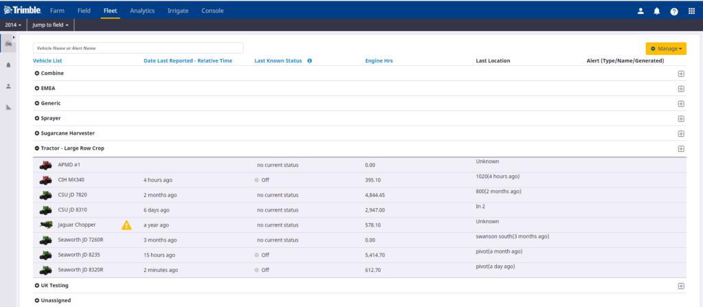
This screen is configurable so that you can choose which information to display about your vehicles – the following information can be displayed:
| Item |
Description |
| Vehicle List |
Allows you to organize your fleet by vehicle group (for example, Tractor – 4WD), name vehicles as required, and move vehicles.

You can do the following:
- Click the
 icon next to a vehicle group to show all vehicles included in this group. icon next to a vehicle group to show all vehicles included in this group.
- Click a vehicle name to display its status. See Vehicle Status screen
|
| Date Last Reported: Calendar Time |
The last time a vehicle reported in, in calendar time. |
| Date Last Reported: Relative Time |
The last time a vehicle reported in, relative to the current time |
| Last Known Status |
The last known status of a vehicle. The options are:
- Stopped: The vehicle has been is stationary for more than 15 seconds.
- Working: The vehicle is moving. When the optional Implement Switch is selected and installed on the DCM-300 modem, Working is defined as the vehicle moving and the implement switch as active.
- Moving: The vehicle is moving but the implement switch is inactive (not working). This state is only reported when the optional work switch is installed for the DCM-300 modem.
- Off: The vehicle’s ignition is turned off.
- Pending (FarmStream only): The vehicle has not yet communicated state information for this time period.
- Speeding: The vehicle’s speed exceeded a defined threshold.
- No GPS (FarmStream only): The vehicle has lost its GPS signal.
- Delayed (FarmStream only): The vehicle is stationary for an extended period of time.
- Rushing (FarmStream only): The vehicle is working but moving too quickly.
|
| Engine Hrs |
The number of hours the engine has been in use. |
| Alert (Type / Name / Generated) |
Display the most recent alert for this vehicle in the past 24 hours. See Alerts, 26 |
| Last location |
The last location the vehicle reported in. If it was in a field, it will show the field name, otherwise it will show the address. |
| Last Reported Speed |
The last reported speed of the vehicle. |
| Vehicle Type |
Type of vehicle. |
| Vehicle Make |
Make of vehicle. |
| Fuel Level |
Fuel level of the vehicle (if reported by the vehicle). |
| Last Operator Name (FarmStream only) |
The name of the last operator to log in to that vehicle. |
| Last Operator Login (FarmStream only) |
The login of the last operator to log in to that vehicle. |
| Manage |
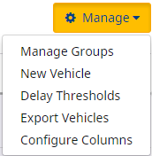
When you click this button, a drop-down list appears. From here you can:
|
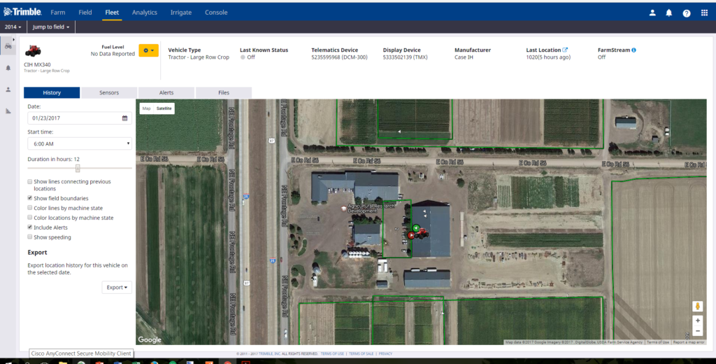
This screen shows the following information for an individual vehicle – to open this screen, click the vehicle name:
| Item |
Description |
| Information banner |
The information banner shows the following information:
- An icon representing the vehicle, with below it the name of vehicle and the group to which it belongs.
- An icon representing the fuel level, if fuel level data is available.
- Type of vehicle.
- Last Known Status of the vehicle. The options are moving, working, stopped, off, pending, rushing, no GPS, speeding, and delayed.
Note: The available status to report depends on the type of Fleet in use and the vehicle setup. For more details, refer to the Feature Chart comparison.
- Telematics Device serial number (traditional Fleet only).
- Display Device used on the vehicle (FarmStream only).
- Manufacturer of the vehicle.
- Last Location of the vehicle at the time the system was updated. If the vehicle was in a field and the user has selected to show location as field name, this will show the field name of the last known field the vehicle was in.
- FarmStream status – shows whether this vehicle is set up for FarmStream or the traditional Fleet setup with the DCM-300 modem as a telematics device (FarmStream on or off).
From the drop-down menu (shown next to the fuel icon), you can now do the following:
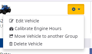
|
| History tab |
This tab allows you to:
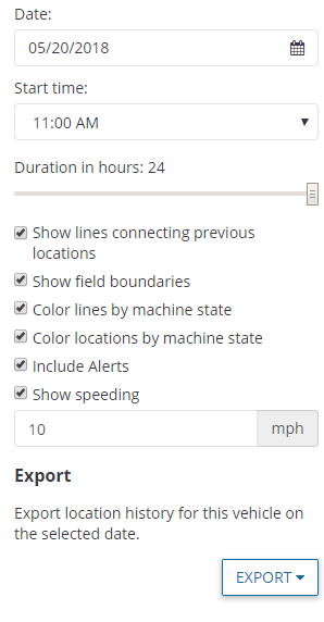
- Select a Date using the date picker.
- Select a Start time from the drop-down list.
- Use the slider bar to set the Duration in hours.
- Select Show lines connecting previous locations to see location and travel routes.
- Select Show Field Boundaries to see field boundaries on the screen.
- Select Color lines by machine state to see the different vehicle states on the connecting lines – depending on the Fleet set up that you are using, the options are Moving, Working, Stopped, Pending, Speeding, Delayed, No GPS, Rushing, and Off.
- Select Color locations by machine state to see the different vehicle states—depending on the Fleet set up that you are using, the options are Moving, Working, Stopped, Off, Pending, Speeding, Delayed, No GPS and Rushing.
- Select Include Alerts if you want alerts to be shown.
- Select Show Speeding if you want speeding indicators to appear on the History page if a vehicle is speeding (based on a user-defined speeding threshold ).
- Set the speeding threshold by entering a value in the field (mph or km/h). Any speed values recorded at or over that threshold will be marked as speeding on the map.
- Click Export to view the vehicle location history in kml or shape file format.
|
| Sensors tab |
This tab shows sensor data.
- The left-hand pane shows high-level information provided by the sensor, such as battery voltage, boost pressure, and temperature. Available sensors will depend on what the vehicle sends to the sensors software – it varies by machine model. The software could show any of the following parameters: Hydraulic Oil Temperature, Hydraulic Oil Pressure, DEF (Urea) level, Engine speed, Coolant Temperature, Engine Oil Pressure, Battery Voltage, Intake Manifold Temperature, Boost Pressure, Engine Load, Engine Oil Temperature, Coolant Level, Electrical Potential, Engine Hours, Fuel Rate, Fuel Level, Engine Oil Level, Hydraulic Oil Level and Hydraulic Oil Filter Restriction Switch:
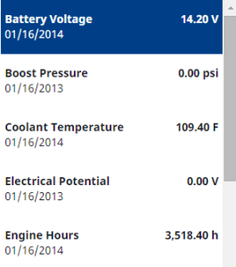
- If you click on an entry in the left-hand pane, it charts the data in the right-hand pane. If required, you can change the date using the date picker at the top of the pane for the current date:

Sensor data requires a connection to the vehicle’s CAN bus. For a list of supported machines, refer to the most current Fleet Utilization Supported Platforms list. If you believe there is an error check the following:
-
- Vehicle might not be connected to a wireless network and reporting data or may not be part of an organization that has a Display Connections (formerly Vehicle Connections) license.
- Vehicle might not have Fleet service enabled.
- No connection to the Vehicle’s CAN bus, or incorrect CAN harness installation.
|
| Alert tab |
Shows a list of alerts for this vehicle only. |
| Files tab |
Shows all files that you downloaded or uploaded to or from your display.See Downloading and uploading files. |
- In the information banner of the vehicle status screen, select Calibrate Engine Hours from the drop-down list:
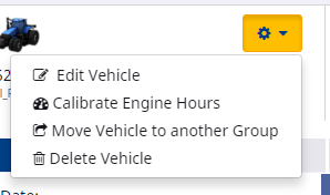
The Calibrate Engine Hours screen appears:
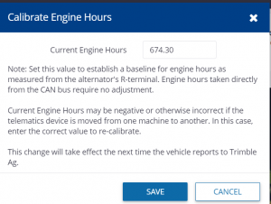
The screen shows the Current Engine Hours. This value establishes a baseline for engine hours as measured from the alternator’s R-terminal. Engine hours taken directly from the CAN bus require no adjustment. If the hours are negative or otherwise incorrect (which may occur, for example, if the telematics device is moved from one machine to another), you can enter the correct value to re-calibrate the system.
- Enter the correct value, if required, and then click Save. If the value is correct, click Cancel.
Any update will take effect the next time the vehicle reports to the Trimble Ag Software solution.
- Select Move Vehicle to another Group from the menu on the Vehicle Status screen for the vehicle you want to move.
- Check the radio button next to the group that you want to move the vehicle to:
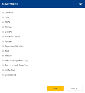
- Click Save.
- In the information banner of the vehicle status screen, select Delete Vehicle from the drop-down list:

The Delete screen appears.
- Click Delete.
The file management feature allows you to access the original data files from the FmX® integrated display, TMX-2050™, GFX-750™, GFX-350™, or the CFX-750™ using the Fleet solution. This eliminates the need for a USB drive for data transfer from the display. Customers can quickly download / upload their field operation data files.
Files can be managed in Fleet from the individual vehicle’s Files tab.
For files to and from an individual vehicle, open the Files tab:
- In the Vehicles tab, click the vehicle name.
- Click the Files tab:

- Select a date from the date picker to view all the available files from a particular day up to the present and then click Apply.
- Click the file name that you want to download. It will default to From Vehicle which shows all files sent from a vehicle.
| Field |
Description |
| Name |
The name of the file. |
| Size |
The size of the file. Files must be less that 50 MB. |
| Date Received |
The date on which the file was received. |
- Save or open the selected file.
To view all files sent to a vehicle for a particular time period, or to upload a file to a vehicle, click To Vehicle:

| Field |
Description |
| Name |
The name of the file. |
| Size |
The size of the file. Files must be less that 50 MB. |
| Status |
The status of the upload process. |
| Date Uploaded |
The date on which the file was uploaded. |
| Resend |
Click to resend the file, if required. |
To upload a file to a vehicle click Upload and then select the required file. Files must be less than 50 MB. This upload feature only works for displays with Office Sync enabled. Displays with AutoSync enabled can’t use the Upload feature.
- Click the Manage button, and then select Manage Groups from the drop-down list,
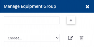
- In the Manage Equipment Group screen, enter a name and then click
 to create a new equipment group. Alternatively, select a group name from the Choose field and click
  to edit an existing group name:
The new group is added to the Vehicles screen.Vehicles and implements can now be assigned to the new group. The new group will only appear on the Vehicles screen once a vehicle has been assigned to it.
- To assign a vehicle to a group, or to move it to a different group select the Move Vehicle option from the Vehicles Status page.
- To add more vehicles to a group with a vehicle already in it, click
 on the same line as the group name on the Vehicles page:
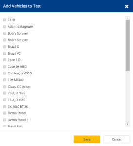
- In the Add Vehicles to <Group> screen, select the vehicle(s) that you want to add to the group and then click Save.
- Implements can be added to groups by going outside of Fleet to the Farm -> Equipment -> Implements screen and editing an implement by clicking on the
 icon. In the edit screen you can select a group for that implement.
- Click the Manage button, and then select New Vehicle from the drop-down list:
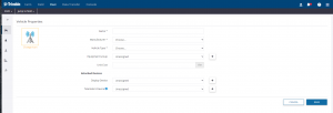
- In the Creating a new vehicle screen, complete the fields as follows:
Icon
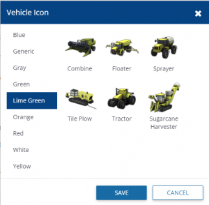
To change the icon:
- Click Change below the icon to change it.
- In the Vehicle Icon screen, click a color (in this example, Lime Green), click the icon that you want to use and then click Save:
| Item |
Description |
| Name |
Enter a name for the vehicle. |
| Manufacturer |
Select a manufacturer from the drop-down list. If the manufacturer does not appear on the list, select Other. |
| Vehicle Type |
Select the vehicle type from the drop-down list. If the vehicle type that you require does not appear on the list, select Generic. |
| Equipment Group |
Select the vehicle group that you want to assign the vehicle to from the drop-down list. You can also leave the vehicle Unassigned.
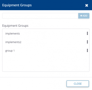
Click + to open the Equipment Groups screen. In this screen you can make changes to existing equipment groups, or add a new group.
|
| Unit Cost |
Enter a unit cost (per hour). |
| Display Connection License |
From this screen you can assign a license to this vehicle, if one is available. See Assigning Display connection license. |
| Display Device |
Select the display from the drop-down list.
For the traditional Fleet set up, the Display Device is required only if the user wants to use the Office Sync or AutoSync service (described elsewhere). When using the FarmStream Fleet set up, an FmX integrated display, GFX-750 display, GFX-350 display or a TMX-2050 display is required.
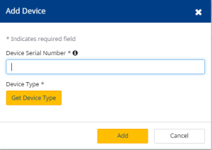
Click Add Display Device to open the Add Device screen. In this screen you can add a display by entering the Device Serial Number.
Note – The device must not already belong to another organization.
|
| Telematics Device (traditional Fleet only) |
Select the DCM-300 modem that will provide the telematics data to the vehicle. (TRADITIONAL FLEET ONLY! DO NOT SELECT A TELEMATICS DEVICE IF USING FARMSTREAM FLEET.)
To do this, select the serial number of the DCM-300 modem from the drop-down list.
Click Add Telematics Device to open the Add Device screen. In this screen you can add a telematics device by entering the Device Serial Number.
Note – The device must not already belong to another organization.

If you select Telematics device and are using Traditional Fleet, an option becomes available that allows you to choose whether to select an implement switch to define working for that vehicle. There is also an option to Select a Delay threshold (see Creating Delay thresholds).

|
- Click Save. The vehicle now appears in the Equipment Group that you selected.
A Display Connection license is required to use most of the features of Fleet. Display Connection licenses can be purchased and assigned to a Display. You can tell on the Vehicles page which vehicles don’t have devices with display licenses assigned by the yellow warning icons.
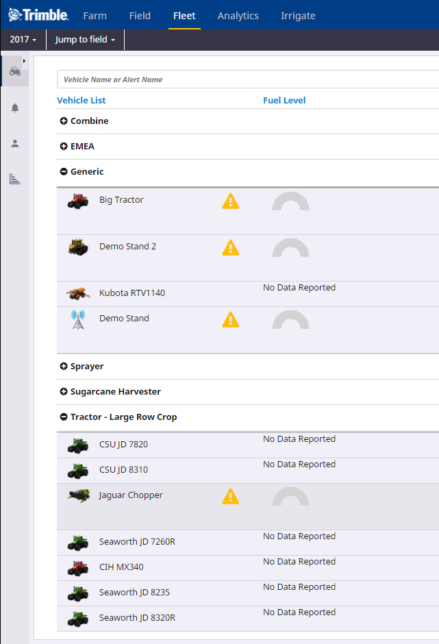
When creating a new vehicle, it will not have a Display Connection license assigned and the screen will notify you if there are any licenses available to assign. If there are no licenses available to assign, contact your reseller to purchase licenses.
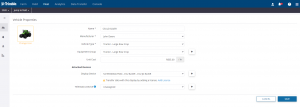
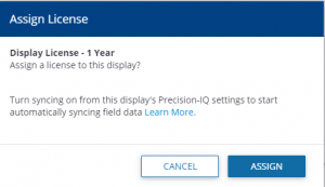
If licenses are available to assign, select the “Add License” option to assign a license to the devices. A window will pop up to confirm you want to assign one of your available licenses to the vehicle. Once a license has been assigned to a vehicle it can’t be moved to another vehicle. Be sure to click on”ASSIGN” and then “SAVE” when done.
If you confirm, the vehicle will show that it has an active Display Connection License with an expiration date:
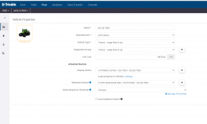
- To edit a vehicle, in the Vehicle Status screen (see Vehicles status screen), select Edit Vehicle from the drop-down list
 :
:
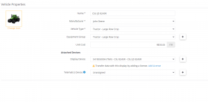
- Make changes to the fields as required and then click Save. For an overview of the fields,see Creating a New Vehicle. In addition, if a telematics device is selected in this screen, you can also select the Delay Response Threshold for the vehicle to determine when a vehicle is delayed and the setting of the implement switch.
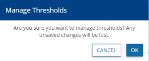
If using Traditional Fleet, there is also a link to go to the Create Delay Threshold screen to create a new Delay Threshold. see Creating Delay Thresholds (traditional Fleet Manager only). If you select Manage Thresholds, a warning appears:
- In the Fleet main page, click
 next to the vehicle group that you want to add vehicles to.
- In the Add Vehicles screen, select the check box next to the vehicle(s) that you want to add to the group:
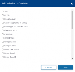
Note – You may not assign a vehicle to more than one group.
- Click Save.
- From the Manage drop-down list, select Delay Thresholds (For traditional Fleet only):
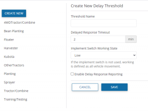
- You can do one of the following:
To view and/or edit an existing Delay Threshold, click a threshold name on the left of the screen, and then make the required changes.
To create a new Delay Threshold, click Create New.
- In both instances, complete or edit the fields as follows:
| Item |
Description |
| Threshold Name |
Enter a suitable threshold name, for example Harvester. |
| Delayed Response Timeout |
Enter the duration in minutes to indicate to the system that the vehicle is delayed. For example, if the vehicle is stopped for three minutes, the system will flag it as having been delayed. |
| Implement Switch Working State |
Select Low or High from the drop-down list. This will define when the vehicle is working.
Note – If the implement switch is not used, Working is defined as all vehicle movement. |
| Enable Delay Response Reporting |
Select this checkbox to allow the operator to enter delay reasons on the display. |
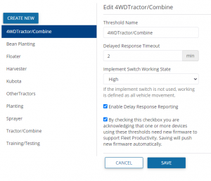
| Agree to firmware update |
A note may appear prompting you to agree to update the DCM-300 firmware if needed to support a new threshold:
|
This dashboard allows you to view your entire Fleet within a single sitemap, along with your Field Task History. This feature is only available with Farmer Core licenses.
To access this feature first locate the Fleet section on the top bar of your organization’s site once you’ve logged in. Hover over this to see a drop down menu and select “Fleet Map” from the list.

Once selecting this you will be directed to the following screen displaying an “Asset List” that details all of your vehicles, a map showing all of your fields grouped into numbers based on site location, and a Field Task List that projects the task history associated with your organization. From this screen you may narrow your search by selecting a specific vehicle or field.
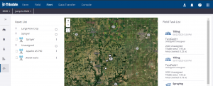
By clicking on individual tasks your sitemap will produce a zoomed in glimpse of that project.
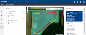
You will also have the option to view further information by selecting “Details” in the upper right corner of the individual tasks.
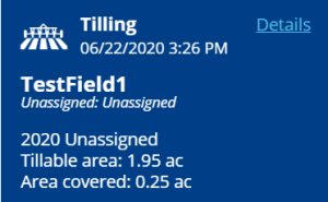
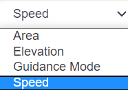
Within the “Details” window you will see a summary of the task specifics. You can toggle through to view map layers based on speed, area, elevation, guidance mode, and other data relevant to the task performed.
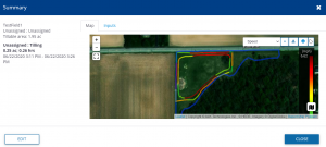
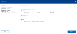
By clicking on “Inputs” within the “Details” window, you will be able to look at the asset totals used.
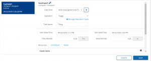
If you would like to modify a task, selecting “Edit” within the “Details” window will allow you to change a variety of different attributes of the task including adding operators, vehicles, implements, and materials.
The Fleet website has an alert mechanism that warns you when a vehicle requires immediate attention:
- Use a Geofence alert (traditional Fleet set up only) to be notified when a vehicle has entered or left a closed boundary that you defined.
- Use a Curfew alert (traditional Fleet set up only) to be notified when a vehicle ignition is turned on during the off-hours you defined.
- Use an Ignition alert (traditional Fleet set up only) to be notified if the ignition is turned on or off for that vehicle.
- Use a Machine alert (FarmStream Fleet set up only) to be notified on fault codes from a machine. See the user interface for supported fault codes.
- Use a Rushing alert (FarmStream Fleet set up only) to be notified if a vehicles goes into the Rushing machine state.
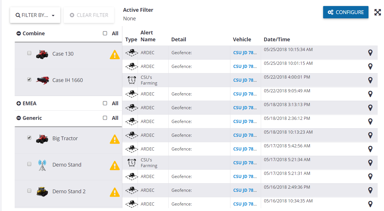
| Item |
Description |
| ❶ |
Filter.
This option allows you to filter your alerts. To do this, select an option from the drop-down list, and you may clear any filters by clicking the CLEAR FILTER option:
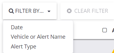 The options are are Date, Vehicle or Alert name or Alert Type. Depending on what you select, other options will pop up to let you further refine your selection. The options are are Date, Vehicle or Alert name or Alert Type. Depending on what you select, other options will pop up to let you further refine your selection. |
| ❷ |
Vehicle list.
This option allows you to show alerts for all or only some vehicles / vehicle groups.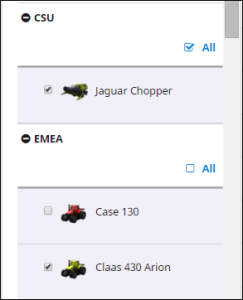
In this example, alerts are shown for all vehicles in the CSU group, but only for one of the vehicles in the EMEA group. Make your selection by selecting or clearing the check boxes and then click Apply. |
| ❸ |
Alerts.
All the selected alerts are shown. The following information is provided for each alert:
- Type: Identified by an icon as curfew, geofence, ignition, machine, or rushing.
- Alert Name
- Vehicle: The vehicle name.
- Date / Time: The date and time the alert was triggered on the vehicle.
- Detail: Any additional details that are available for that alert.
Note – The screen displays the most recent 100 alerts that match the filter specifications. Scroll to the bottom of the screen and click Show More if required. |
| Configure |
When you click this button, a list of the alerts appears:

This contains the alert type, the name of alert, any alert detail, a pin with a link to the location of the alert, as well as the Vehicle (number of vehicles to which the alert has been applied), and Contacts.
You can do the following:
- Click
 to review or edit the alert details, see Editing alert details to review or edit the alert details, see Editing alert details
- Click
 to delete the alert, see Deleting an alert. to delete the alert, see Deleting an alert.
- Click Manage. When you click this button, a drop-down list appears. From here you can:
|
- In the Alert tab, click Configure.
- From the Manage drop-down list, select New Alert from the drop-down list.
- In the Creating Configured Alert screen, complete the fields as follows:
| Section |
Description |
| Alert Data |
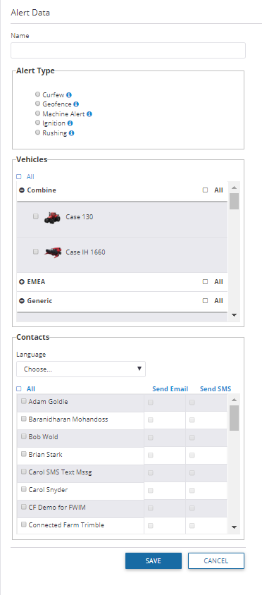
- Name: Enter a name for the alert. This is the name that is used in the main screen of the Alert tab.
- Alert Type: Select the required alert type. The options are Geofence, Curfew, Ignition, Rushing, and Machine. The fields that appear in the following section depend on the selection you make here.
- Frequency: The minimum frequency at which this alert will be sent via text or email. It can be set in minutes or hours, with a range between 3 minutes and 24 hours.
This setting only limits alerts received over email or text and not the alerts shown on the Alerts page.
|
| Alert Details: Geofence
(traditional Fleet only) |
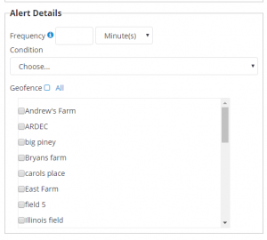
- Condition: Select the condition that will trigger the geofence alert from the drop-down list. The options are Site Entry and Exit, Site Entry, or Site Exit.
Note – For each geofence alert you can select to trigger the alarm for entry to or exit from a boundary, or both. Exit triggers can be used to signal completion of work in a given area or to signal possible misappropriation of a vehicle from its area of use. Entry triggers can be used to signal if a vehicle has entered a restricted area.
- Geofence: Select the checkbox next to the geofence area(s) to which the alert applies. You must create a geofence before you can create a geofence alert.
|
| Alert Details: Curfew
(traditional Fleet only) |
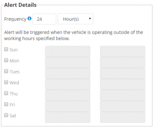
Frequency is same for all types of alerts as described above. Enter the working hours for each day, as required, during which the vehicle may be turned on. The alert is triggered if the ignition is turned on outside the defined working hours.
If you select the check box next to the day, the default working hours (7:00 am to 5:00 pm) are inserted, but these times can be changed as required. If you click in any field, a list of times appears from which you can make a selection.
If a day’s check box is not selected (as shown here for Sunday and Saturday), the alarm is triggered automatically if the vehicle is turned on.
Only one curfew alert may be defined per vehicle. |
| Alert Details: Ignition
(traditional Fleet only) |
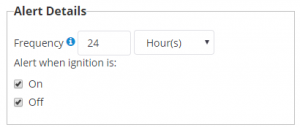
Select the appropriate checkbox – the alert will be triggered accordingly. |
| Vehicles |
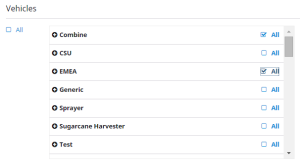
Select the check box next to each vehicle to which the alert will apply. If you select a Vehicle Group (for example Sprayer), all vehicles that belong to that group will be included in the alert.
To select all vehicles, click the All check box. |
| Alert details: Rushing
(FarmStream Fleet only) |
Rushing alerts require an FmX display with firmware version 9.27 or higher, a TMX-2050 with firmware 4.3.1 or higher, or a GFX-750 display with firmware 1.5 or higher. The display mush have a Display Connections (formerly Vehicle Connections) license assigned to it. |
| Alert details: Machine Alerts
(FarmStream Fleet only) |
Choose the manufacturer that you want to be alerted for receiving fault codes on. See the Fleet interface for supported manufacturers. |
| Contacts |
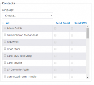
Select the check box next to the name of the contact(s) who should receive the alert. The program allows you to enter an email address for the alert. Alerts may also be sent as a text if you enter the email address for the text functionality on your phone. See Creating a contact. To select all contacts, click the All check box. |
- Click Save.
- In the Alerts tab, click Configure.
- In the list of configured alerts, click
 .
.
- Make any required changes and then click Save. For a list of the fields, see Creating an alert.
- In the Alerts tab, click Configure.
- In the list of configured alerts, click
 next to the alert that you want to remove:
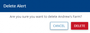
- Click Delete.
- In the Alerts tab, click Configure.
- From the Manage drop-down list, select Geofences.
- In the Geofences screen you can do the following:
- Go to Manage -> Geofences. In the Geofences screen, click Create.
- In the Geofence screen, enter a Name for the geofence.
- Zoom in on the area where you want to create the geofence.
- Select one of the Drawing tools. Click the map to create a point to start the geofence. Follow the instructions given for each drawing tool to create a shape.
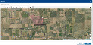
If you make a mistake, you may do any of the following:
- Click Cancel and then start again. This will remove all points. Depending on what drawing tool you are using, you may be able to:
-
- Move points by dragging them to a new location.
- Delete points by selecting the point and then clicking X.
- Click Save. The geofence will now be available for selection in the Alerts screen. Once you have saved the geofence, you will no longer be able to edit the points.
Note – The Fleet website limits geofence creation to 100 geofences per organization. A geofence cannot have more than 50 points.
- In the list of geofences, click
 next to the geofence you want to view or edit.
- If required, you can change the Name of the geofence and then click Save.
Note – When using the point-based drawing tool to create a geofence, you can only edit the points once you have completed the geofence boundary, but before you save it.
- In the list of geofences, click
 next to the geofence that you want to remove:
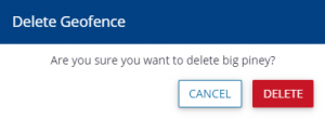
- Click Delete. Once a geofence is deleted, it is removed from all alerts where it was selected.
- In the Alert tab, click Configure.
- From the Manage drop-down list, select Contacts.
- In the Contacts screen, you can do the following:
- From the drop down menu next to each contact, you may select to Edit or Delete a contact – see Editing a contact or Deleting a contact.
- From the Manage menu, you may choose to Add Contact, Send Operators to Vehicles, Print Operator QR Codes, or manage the Operator Display Sign In for that contact. Refer to each of the corresponding sections for more details.
- To get to the Contacts page, click on Alerts, then click on Configure, then from the Manage menu, select Contacts
- On the Contacts page, in the list of contacts, click on the menu to the right of the contact you want to view or edit and select “Edit.”
- If required, make any changes and then click Save. For a list of the fields, see Creating a contact
- To get to the Contacts page, go to Alerts, then click on Configure, then from the Manage menu, select Contacts
- From the Contacts page, In the list of contacts, click the menu to the right of the contact that you want to remove:
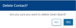
- Click Yes. Once a contact is deleted, it is removed from all alerts where it was selected.
- To get to the Contacts page, go to Alerts, then click on Configure, then from the Manage menu, select Contacts
- In the Contacts page, click Manage -> Add Contact:
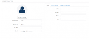
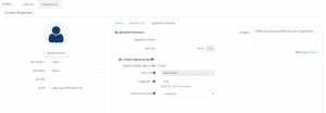
- Complete the fields in the screen. If you are an org administrator, you will be able to assign access levels in the web software for a contact. Org admins can also make a contact an operator and give them a login and an access level on a display. “Full Access” operators can edit and delete resources on a display, while “Select Only” operators can view. Non-Admins can create contacts but not assign access levels.
- Click Save.
To get to the Contacts page, go to Alerts, then click on Configure, then from the Manage menu, select Contacts
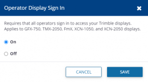
From the Contacts page, you can turn on Operator Display Sign In by going to the Manage menu and selecting Operator Display Sign In. Turning this feature on will require all operators to sign in to access Trimble displays in your organization. This feature requires AutoSync to be enabled.
This screen shows the following information:
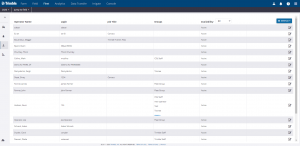
| Item |
Description |
| Operator Name |
The name assigned to the user by the administrator. |
| Login |
Login name. The login is used for the display – it is also the unique identifier for duplicate names. |
| Job Title |
The job title of the operator. |
| Groups |
The group(s) (if applicable) that the operator is assigned to. |
| Availability |
The options are All, Active, and Inactive. You can filter the list by selecting an option from the drop-down list next to the column header. |
| Manage Menu |
This menu allows you to create a new Operator, a new Operator Group, Send operators to vehicles, Import/Export Operators, and Print QR codes. See corresponding sections for more information on each function. |
Creating a new Operator Group
- From the Operators page, from the Manage menu, click on New Operator Group. Enter a name for the new operator group and then click on +ADD.
- OR – from the Alerts page, click on Configure, then from the Manage menu, select the Contacts page. From there, you will see a list of contacts. Select the Edit option from the menu to the right of a contact to edit that contact. Click on the Equipment Operator tab, and select Manage Groups:
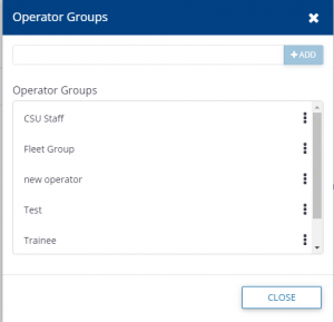
- Enter a name for the new operator group in the empty box and then click on +ADD. If you are coming to this dialog from the Alerts page, groups can also be edited or deleted from this dialog box.
- In the Operators tab, select New Operator from the Manage drop-down list. This can also be accessed from the Farm menu, under People.
- In the Contact Properties screen, complete the fields and click Save. To make the user an operator, be sure to click on “Equipment Operator” under the Equipment Operator tab. Operator login and permissions level can also be assigned from this tab.

Editing operator details
- In the list of operators, click the edit symbol next to the operator you want to view or edit.
- Change any fields, as required and then click Save.
Operators can be imported from a .csv or .xls file, or from an existing organization. The following is an example of a .csv or .xls file import:
| LoginID |
First Name |
Last Name |
Job Title |
Group |
| BSmith1 |
Bob |
Smith |
Operator1 |
GroupA |
| JSmith1 |
John |
Smith |
Operator1 |
GroupB |
- Operators are added to the Operator list or Group specified if the Login ID, Last Name, and First Name fields are specified and the Login ID does not already exist. If any row fails to import, the import will continue with the next row.
- The check for Login ID duplication is not case sensitive (that is, the system will not create JSmith1 if jsmith1 already exists).
- You must create groups in the user interface before you import operators.
- If the Group does not exist the operator is not imported and the row fails.
- If no Group is specified in the .csv file, the operator is created and added to the Unassigned list.
- Group is a match if it contains the same characters, regardless of case (that is, GroupA or groupa).
- Job Title is added for each job title in the file and depends on the number of characters. It is a match if it contains the same characters, regardless of case (for example, Foreman or foreman).
An Import report is created that includes the following:
- Any rows that did not import due to insufficient or duplicate data.
- The number of successful logins created.
- The groups that could not be found during the import.
To import operators from a .csv or .xls file:
- In the Operators tab, select Import Operators from the Manage drop-down list.
- Click From a File and then click Choose File.
- Navigate to and select the required file and then click OK.
- Click Import.
- Click Done.
- In the Operators tab, select Export Operators from the Manage drop-down list.
- You may be prompted to save or open the Operators.csv file.
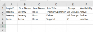
If you open the file, you will see all information entered in the system earlier in the order Login ID, First Name, Last Name, Job Title, Group and Availability:
This feature is only enabled for FmX integrated displays on a vehicle with an active Display Connection (formerly Vehicle Connection) license. TMX-2050, GFX-750, and GFX-350 displays automatically download all operators when they have connectivity and are visible in the Operator app on the display.
- In the Operators tab, select Send to Vehicles from the Manage drop-down list—this will send a list of operators to the display on the selected vehicle for login purposes:
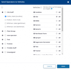
- In the column on the left, select a group (and by definition, all members of that group, see Trainee, above) or individual operators (see CSU Staff) by selecting the check box next to the user/group name.
- In the Vehicles column on the right, select a Vehicle Group or individual vehicle(s).
- Click Send to assign the selected Operator(s) to the selected Vehicle(s).
- Click X to close the screen.
- In the Operators tab, select Print QR Codes from the Manage drop-down list.
- In the Print QR Codes screen, select the staff for whom you want to print the QR codes. These codes are used to log in to a display:
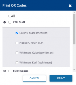
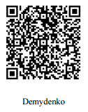
- Click Print. The QR code is printed, with the name of the person for whom it is intended:
The Fleet Utilization reporting feature allows users to evaluate the performance of their machines over a chosen 24 hour period. Vehicle status is displayed, showing states such as moving, working, off, or stopped. The time in each state is calculated and displayed:
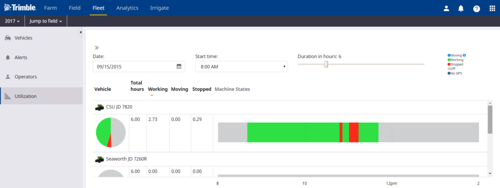
You can now compare the utilization of each vehicle over the selected time.
See Comparing utilization.
- In the Utilization tab, enter a Start date, time and duration.
- Select the group, and within that group, the vehicles for which you want to compare utilization:
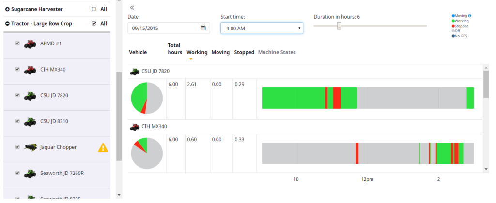
A graphic appears comparing the vehicles for the selected period. To decode the graphic, use the indicators (for example, Green = Working) that appear at the top of the screen.
For the traditional setup of Fleet, the vehicle states are Working, Moving, Stopped, and Off.
For the FarmStream setup of Fleet, the vehicle states are Working, Moving, Stopped, Off, Speeding, Rushing, No GPS, and Delayed.
If Fuel rate is supported by the vehicle CAN bus, then Fuel Consumption can be reported in the utilization page and will show up in the tool tip as you hover over the different states.
The Fleet website can show vehicle information from some external applications, including Raven Slingshot and JD Link. To set up a vehicle from a third party application,
Go to the Data Transfer page and select Settings and API Connections.
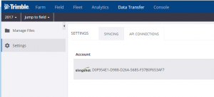
On this page, you will see any existing connections between your organization and an external account/
To add another connection to an external account, click on “+ Add Account” and select the type of external account to add.
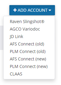
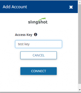
For each account, you will need to supply credentials for accessing the third party website. For Raven Slingshot, you will need to enter an Access Key that is generated on the Slingshot website. Contact Raven to purchase the Access Key.
For Raven Slingshot accounts linked to your Trimble Ag Software account, you will see any Raven devices in the list of available devices and you can link it to a vehicle in your Trimble Ag Software account.
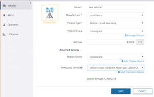
You will then be able to see vehicles from your Raven Slingshot account in Fleet Manager.
Agriculture Business Area
Trimble Inc.
Trimble Agriculture Division
10368 Westmoor Drive
Westminster, CO 80021, USA
trimble_support@trimble.com
agriculture.trimble.com
Copyright and Trademarks
© 2020, Trimble Inc. Trimble, the Globe & Triangle logo, Farm Works Software, and FmX are trademarks of Trimble Inc., registered in the United States and in other countries. Connected Farm, Farm Works, GFX-350, GFX-750, and TMX-2050 are trademarks of Trimble Inc. Microsoft and Internet Explorer are either registered trademarks or trademarks of Microsoft Corporation in the United States and/or other countries. All other trademarks are the property of their respective owners.
Release Notice
This is the June 2020 release of the FarmStream Fleet Help Guide.
Product Warranty Information
For applicable product warranty information, please refer to the Warranty Card included with this product, or consult your Trimble reseller.


